CHAP 5, SEC X X X I II
A S S E M B LY
P A R 227, STEPS 5 1 - 5 4
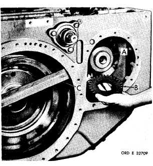
F i g u r e 2 9 0 ( S t e p 5 1 )
Install spacer (A) and brake coolant oil pump
d r i v e g e a r ( B ) . R e m o v e w o o d e n b l o c k ( C)
f r o m h o u s i ng
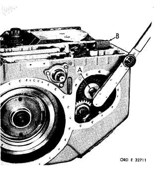
Figure 291 (Step 52)
Install lock plate (A) and 3/4-16 x 2-3/4 self-
locking bolt (B), finger-tight at this time. In-
stall output driven gear shaft (C).
1 7 6
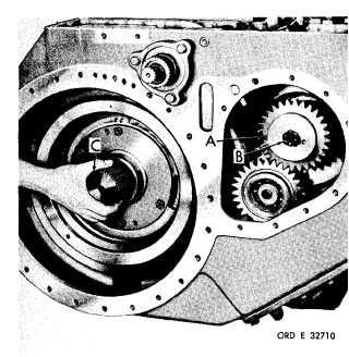
Figure 292 (Step 53)
Using a l-inch wrench, tighten brake coolant
p u m p d r i v e g e a r r e t a i n i n g s e l f - l o c k i n g b o l t
(A) to 337-385 pound-feet torque. Use a block
(B) of soft metal between the output transfer
drive gear and rear housing to prevent rotation.
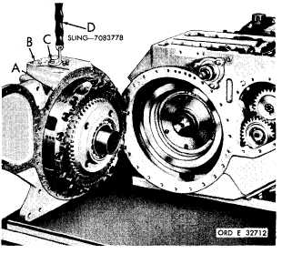
Figure 293 (Step 54)
Install gasket (A) on right- output subassembly
(B). Using a 3/8-16 x 1-1/2 bolt (C) and sling
(D), install subassembly (B).
|
|