*C2
C H A P 5, S E C
X X X l ll
A S S E M B L Y
P A R 2 2 8 , S T E P S 3 - 6
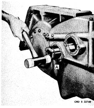
Figure 330 (Step 3)
Install idler cluster gear spindle assembly (A).
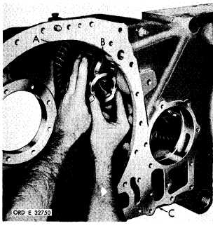
Figure 331 (Step 4)
Install input transfer cluster gear and bearing
a s s e m b l y ( A ) a n d s p a c e r ( B ) , a l i n i n g p a r ts
with the spindle bore in housing (C).
1 8 6
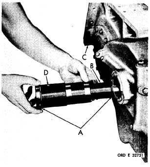
Figure 332 (Step 5)
I n s t a l l O - r i n g s e a l s ( A ) o n t o c l u s t e r g e a r
spindle (B). Install spindle (B) with seals (A)
into housing (C), and cluster gear and bear-
i n g a s s e m b l y . B e s u r e t h a t o i l h o l e ( D ) in
spindle is up.
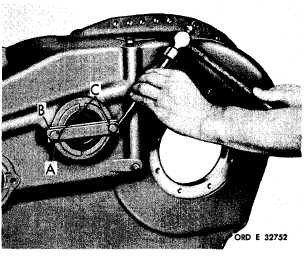
Figure 333 (Step 6)
Install lock strap (A), lock strip (B) and two
3/8-16 x 1 bolts (C). Using a 9/16-inch wrench,
t o r q u e b o l t s t o 2 6 - 3 2 p o u n d - f e e t . B e n d c o r -
ners of strip (B) against the bolt heads.
|
|