*C2
P A R 2 2 8 , S T E P S 2 3 - 2 6
A S S E M B LY
C H A P 5, S E C X X X I I I
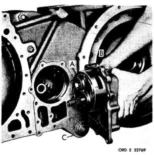
Figure 350 (Step 23)
Install input oil pump assembly (A) and gasket
(B) into transfer housing (C).
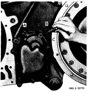
Figure 351 (Step 24)
Install six 3/8-16 x 1-1/2 (A) and five 3/8-16
x 3-3/4 bolts (B) with lock washers to retain
i n p u t o i l p u m p a s s e m b l y ( C ) . U s i n g a 9 / 1 6-
inch wrench, torque bolts to 26-32 pound-feet.
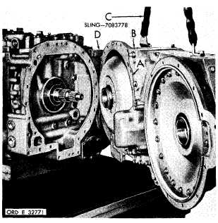
Figure 352 (Step 25)
I n s t a l l g a s k e t ( A ) o n i n p u t t r a n s f e r h o u s i ng
assembly (B). Using sling (C) install housing
assembly (B) onto transmission assembly (D).
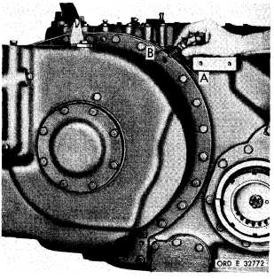
Figure 353 (Step 26)
Install sixteen 7/16-14 x 1-1/2 converter hous-
i n g - t o - i n p u t t r a n s f e r h o u s i n g a s s e m b l y b o l ts
( A ) w i t h l o c k w a s h e r s ( B ) . U s i n g a 5 / 8 - i n ch
wrench, torque bolts to 42-50 pound-feet.
1 91
|
|