*C2
C H A P 5, SEC X X X I II
A S S E M B LY
P A R 2 2 8 - 2 2 9
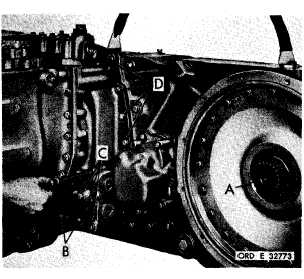
Figure 354 (Step 27)
Install engine coupling shaft (A). Install two
7/16-14 x 5-1/4 (B), four 7/16-14 x 6 (C) and
f o u r 7 / 1 6 - 1 4 x 1 - 1 / 2 c o n v e r t e r h o u s i n g - t o-
i n p u t t r a n s f e r h o u s i n g b o l t s ( D ) w i t h l o ck
w a s h e r s .
U s i n g a 5 / 8 - i n c h w r e n c h , t o r q u e
bolts to 42-50 pound-feet.
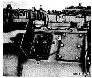
Figure 355 (Step 28)
R e m o v e b r a k e i n s p e c t i o n c o v e r s ( A ) w h i c h
w e r e t e m p o r a r i l y i n s t a l l e d . R e f e r t o s e c.
XXXIV, par. 234 for a final brake adjustment.
I n s t a l l g a s k e t s ( B ) a n d c o v e r s ( A ) . S e c u re
c o v e r s w i t h t w e l v e 3 / 8 - 1 6 x 1 - 1 / 8 b o l t s ( C)
with lock washers. Using a 9/16-inch wrench,
torque bolts to 26-32 pound-feet.
2 2 9 . A S S E M B L Y S T E P S – L E F T - A ND
R I G H T - O U T P U T D R I V E A S S E M B L I ES
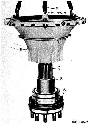
Figure 356 (Step 1)
Install gasket (A) and sleeve (B) onto output
s h a f t a s s e m b l y ( C ) . U s i n g s l i n g ( D ) , i n s t a ll
output drive housing (E).
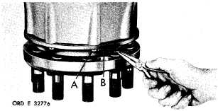
Figure 357 (Step 2)
Install eight 7/16-20 x 1-1/4 bolts (A). Using
a
5/8-inch
wrench,
torque
bolts
to
50-60
p o u n d - f e e t .
I n s t a l l l o c k w i r e ( B ) t h r o u g h
bolts (A).
1 9 2
|
|