*C2
P A R 2 2 9 , S T E P S 3 - 6
A S S E M B LY
C H A P 5, SEC X X X I II
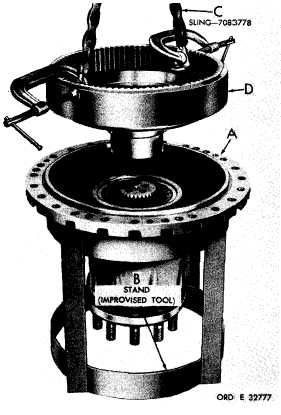
Figure 358 (Step 3)
Position assembled housing (A) on stand (B).
Using sling (C),install output drive planetary
r i n g g e a r ( D ) .
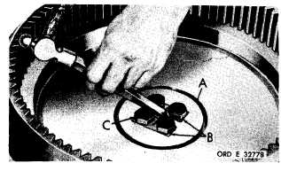
Figure 359 (Step 4)
Install lock plate (A) and secure with two lock
strips (B) and four 5/8-18 x 2-1/2 bolts (C).
U s i n g a 1 5 / 1 6 - i n c h w r e n c h , t o r q u e t h e b o l ts
t o 1 3 4 - 1 6 0 p o u n d - f e e t . B e n d a t a b o f l o c k
strips (B) against the head of each bolt (C).
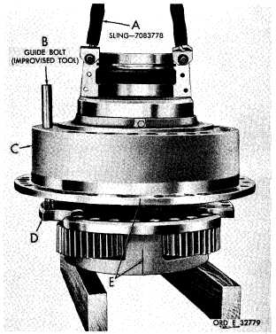
Figure 360 (Step 5)
U s i n g s l i n g ( A ) a n d a h e a d l e s s 7 / 8 - 1 4 g u i de
b o l t ( B ) , i n s t a l l s a d d l e a s s e m b l y ( C ) o n to
planetary carrier assembly (D), alining index
m a r k s ( E ).
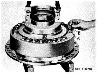
Figure 361 (Step 6)
Remove headless guide bolt.
ers (A) and 24 bolts (B). Do
at this time.
1 9 3
|
|