C H A P 5, SEC X X X I II
A S S E M B L Y
P A R 229, STEPS 7 - 1 0
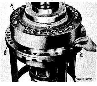
Figure 362 (Step 7)
Install saddle and planetary assembly (A) onto
output drive housing (B), alining index marks
Install three 5/8-18 x 1-1/4 screws (C).
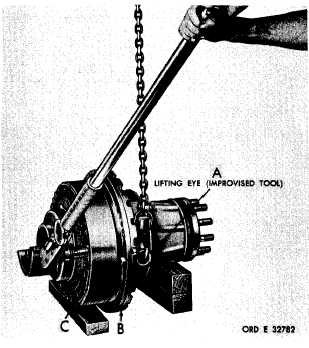
Figure 363 (Step 8)
Using lifting eye (A) and hoist to prevent out-
put drive assembly (B) from turning, tighten
2 4 b o l t s ( C ) . U s i n g a 1 - 1 / 8 - i n c h w r e n c h ,
torque the bolts to 575-650 pound-feet.
1 9 4
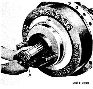
Figure 364 (Step 9)
I n s t a l l i n p u t s h a f t ( A ) , m e s h i n g i t w i t h t he
planetary pinions.
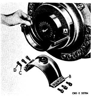
Figure 365 (Step 10)
Install alinement ring (A). Install saddle cap
a s s e m b l y ( B ) . I n s t a l l l o o s e l y s i x 3 / 8 - 2 4 x
1-1/4 bolts (C) with lock washers (D), since
cap assembly is removed when unit is install-
e d i n v e h i c l e .
N o t e . A l i n e m e n t r i n g ( A ) i s
used on only the right (shorter) assembly.
|
|