P A R 2 3 3 - 2 3 4
T E S T S A N D A D J U S T M E N T S
C H A P 5, SEC X X X I V
brakes will stop such rotation when the power
train is functioning properly.
(2) In all four forward gears, when no
steer is applied, the power train outputs should
r o t a t e c l o c k w i s e , a s v i e w e d f r o m t h e r i g ht
side of the power train.
(3) In both reverse gears, when no steer
is applied, the power train outputs should ro-
t a t e c o u n t e r c l o c k w i s e , a s v i e w e d f r o m t h e
right side of the power train.
(4) In forward gears (first and second),
i n c l u t c h - b r a k e f u l l - r i g h t s t e e r , t h e r i g h t
power train output should stop while the left-
output rotates clockwise, as viewed from the
right side of the power train.
(5) In forward gears (first and second),
in clutch-brake full-left steer, the left-power
train output should stop while the right output
r o t a t e s c l o c k w i s e , a s v i e w e d f r o m t h e r i g h t
side of the power train.
(6) In forward gears (third and fourth),
i n g e a r e d f u l l - r i g h t s t e e r , b o t h p o w e r t r a in
o u t p u t s s h o u l d r o t a t e c l o c k w i s e , a s v i e w ed
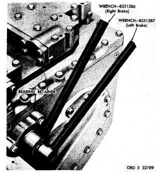
Figure 370. Right- and left-brake adjusting wrenches,
properly positioned
f r o m t h e r i g h t s i d e o f t h e p o w e r t r a i n . T he
l e f t o u t p u t s h o u l d r o t a t e 0 . 4 7 7 t i m e s f a s t er
than the right.
(7) In forward gears (third and fourth),
in geared full-left steer, both power train out-
puts should rotate clockwise, as viewed from
the right side of the power train. The right
output should rotate 0.477 times faster than
the left.
( 8 ) I n r e v e r s e 1 , clutch-brake full-
steer, the right output should stop when steer-
i n g r i g h t . T h e l e f t o u t p u t s h o u l d s t o p w h en
steering left. The opposite output should ro-
t a t e c o u n t e r c l o c k w i s e , a s v i e w e d f r o m t he
right side of the power train.
(9) In reverse 2, geared full-steer, the
right output should slow during right steer.
The left output should slow during left steer.
R o t a t i o n o f b o t h o u t p u t s s h o u l d b e c o u n t e r-
c l o c k w i s e , a s v i e w e d f r o m t h e r i g h t s i d e of
the power train.
2 3 4 . A D J U S T M E N T S
a . B r a k e L i n k a g e
(1) Disconnect the vehicle brake linkage
from the transmission. Check vehicle linkage
to see that it is not binding.
( 2 ) P o s i t i o n t h e v e h i c l e b r a k e c o n t r o l
in fully released position. Adjust vehicle link-
age until it can be freely connected to the trans-
m i s s i o n .
Secure the linkage.
b . B r a k e s
(1) Power train installed in vehicle and
i n s e r v i c e.
( a ) B r a k e l i n k a g e m u s t b e p r o p e r ly
a d j u s t e d a s o u t l i n e d i n a , a b o v e , b e f o r e a t-
tempting this brake adjustment when the brake
apply levers (components of brake linkage) are
c o n n e c t e d .
( b) If brake apply levers are connect-
e d , p e r m a n e n t l y s c r i b e o r t e m p o r a r i l y m a rk
both levers so that the marks aline with the
Release mark on the bearing retainer (fig. 370).
1 9 9
|
|