C H A P 5, SEC X X X I V
T E S T S A N D A D J U S T M E N TS
P A R 2 3 4
( c) With the brakes fully applied, ob-
( d ) I n s t a l l i n s p e c t i o n c o v e r g a s k e t s,
serve the position of the marks on the levers
inspection covers, lock washers and bolts.
in relation to the marks on the bearing retainer.
( d ) If the index marks on the levers
rotate to the Apply mark on the retainer but
not to the Readjust mark, the brakes are satis-
factorily adjusted.
( e ) If the index marks on the levers
do not rotate to the Apply mark or if they ro-
tate to the Readjust mark, the brakes must be
r e a d j u s t e d .
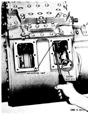
( f ) To adjust the brakes, remove the
inspection covers at the rear of the transmis-
sion rear housing and rotate the adjusting nuts
by inserting a screwdriver in the slots in the
n u t s ( r e f e r t o f i g . 3 7 1 ) . C l o c k w i s e r o t a t i on
will shorten the lever travel (tighten brakes).
C o u n t e r c l o c k w i s e r o t a t i o n w i l l l e n g t h e n t he
lever
travel
(loosen
brakes).
Adjust
both
b r a k e s u n i f o r m l y s o t h a t , w i t h b r a k e s f u l ly
applied, both marks on the levers aline with
the Apply mark on the bearing retainer. Re-
p l a c e i n s p e c t i o n c o v e r s.
N o t e . If the brake linkage is not in-
stalled, the brakes may be adjusted
u s i n g t h e s a m e p r o c e d u r e s a s o u t -
lined in ( a) through (f), above, except
that wrenches 8351386 and 8351387
may be used to apply the brakes (fig.
3 7 0 ) . T h e b r a k e s s h o u l d b e a p p l i ed
w i t h a p p r o x i m a t e l y 9 0 p o u n d - f e et
t o r q u e .
( 2 ) N e w o r r e b u i l t p o w e r t r a i n n o t in
v e h i c l e.
( a ) Remove inspection covers from the
rear of the transmission rear housing.
( b) Insert gage 8351213 into the slot
i n t h e b r a k e a n c h o r , r i n g , a n d b e t w e e n t he
brake apply-rotating ring and the first brake
plate (fig. 371).
( c) Rotate the adjusting nut until gage
8351213 is snug between the apply ring and
b r a k e p l a t e.
T h e a d j u s t m e n t m u s t n e i t h er
bind the gage nor leave it loose. Adjust both
brakes by this method.
c. Shift Control Linkage
—
(1) The linkage, connecting the selector
valve shaft (fig. 368) with the operator’s shift
c o n t r o l , s h o u l d b e a d j u s t e d c a r e f u l l y . W h en
t h e d e t e n t i n t h e c o n t r o l v a l v e a s s e m b l y is
seated, the power train is in the range to which
the shift indicator points. The operator’s con-
trol must be in a corresponding position.
(2) To adjust the linkage, disconnect it
at one point.
Place the control valve in neutral
so that the detent seats and place the operator’s
shift control in neutral position. Adjust the
linkage so that it can be reconnected without
moving either the control valve or operator’s
shift
control.
T r y t h e c o n t r o l t h r o u g h a l l
range positions, making sure that the detent
seats in each.
d . S t e e r C o n t r o l L i n k a g e
(1) Proper adjustment of the steer link-
Figure 371. Adjusting transmission brake
2 0 0
|
|