TM 9-2520-272-34&P
4-15
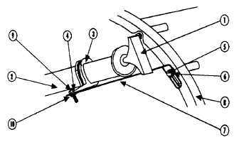
INSTALL OIL FILL TUBE ASSEMBLY
(SHEET 10 OF 11)
5 Coat o-ring (13) with transmission oil.
6 Install new o-ring (13) on elbow (11). Install o-
ring (13) until it seats on back up washer on
elbow (11).
7 Using your hands, in the direction of the bend in
the elbow (11), back off lock-nut (17), on the
elbow (11), as far as possible.
8 Inspect back up washer and o-ring (13) to insure
the back up washer is not loose and the o-ring
(13) and back up washer are pushed up, in the
direction of the bend in the elbow (11) as far as
possible.
9 Using your hands, screw elbow (11) and o-ring
(13) into the adapter (14) until the back up
washer makes contact with the adapter (14).
Light wrenching may be necessary to obtain
seating of the backup washer. If necessary use a
1-1/16 wrench for this purpose.
CAUTION:
For alignment of oil level tube assembly and
elbow, elbow is to be unscrewed by the required
amount. Do not align by turning elbow in a
10
To align the elbow (11) with the oil level tube
assembly (2), unscrew elbow (11) by the
required amount, but not by more than one full
turn. Light wrenching may be necessary to
obtain seating of the backup washer. If
necessary use a 1-1/16 wrench for this purpose.
NOTE:
Should repair not include installation of oil level
fill tube, position the elbow pointing towards
center of the LH Output Shaft. Using a 1-1/16
wrench to hold elbow and a 1-1/4 crowfoot and
torque wrench, torque nut on elbow to 79 87 lb
ft( 107118 N•m).
11 Using hands, install oil level fill tube (2) on elbow
(11).
12 Using a 1-1/16 wrench to hold elbow (11) and a
1-1/4 crowfoot and torque wrench, torque nut on
elbow to 79 87 lb ft(107 118 N•m).
Go to Sheet 3.
Para. 4-15, Task 4
Change 2 4-63.2
|
|


