TM 9-2520-272-34&P
4-21.
ASSEMBLE RIGHT END COVER ASSEMBLY
(SHEET 22 OF 22)
5
X200-4 Using crowfoot and torque wrench, tighten
elbow (4) to 127 - 140 lb-ft (172 - 190 Nm) in the
position shown in illustration. (When oil line is
installed,
elbow
(4)
may
be
repositioned
to
accommodate oil line.)
6
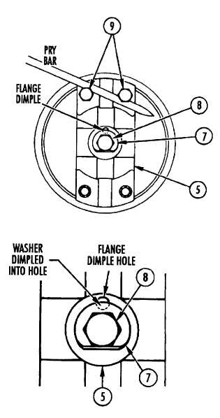
Install output flange (5) in output shaft (6) located in
right end cover (3).
7
Install new tab washer (7) on 1/2-20 x 3-1/4 inch bolt
(8) with bent tab on washer toward head of bolt.
8
Install bolt (8) through center of flange (5) and into
center of output shaft (6). Install bolt finger tight.
9
Using 3/4 inch socket, install two 1/2-20 x 3 inch
bolts (9) in tapped holes at either end of output
flange (5) until bolts are flush with inner surface of
flange.
10 Using one hand, hold pry bar between two bolts (9)
to prevent flange (5) from turning.
CAUTION
Do not install washer so that tab is over dimple in
flange. To prevent bolt from turning, tab must be
against flat of bolt and washer must be dimpled
into flange dimple hole. When tab of washer is
at dimple hole, washer cannot be dimpled. Bolt
retaining flange to output shaft may then loosen.
11 Using 3/4 inch socket and torque wrench, tighten bolt
(8) to 72-86 lb-ft (98-117 Nm).
12 Using 3/4 inch socket, remove two bolts (9) from
flange (5).
NOTE
Do not bend the tab of washer (7) against flat of bolt
(8) at this time.
13 Using punch and hammer, punch dimple in washer
(7). Dimple must depress washer into dimple hole in
flange (5).
FOLLOW-ON PROCEDURE: Install right end cover
assembly. Refer to paragraph 4-16.
End of Task 8
Para. 4-21, Task 8
Change 2 4-147
|
|


