TM 9-2520-272-34&P
4-30 ASSEMBLE CENTER HOUSlNG
29
30
31
32
33
34
35
36
37
(SHEET 7 OF 21)
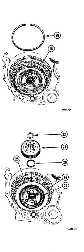
Using feeler gage, measure space between piston
housing assembly (16) and top of retaining ring groove
in range pack bore of center housing. Select retaining
ring (19) from table.
For Measured Distance
Select Ring
0.149-0.152 inch
6884274
(3.79-3.88 mm)
0.153-0.155 inch
6884273
(3.89-3.96 mm)
0.156-0.158 inch
6884275
(3.97-4.03 mm)
0.159-0.161 inch
6884276
(4.04-4.08 mm)
Using screwdriver, install selected retaining ring (19).
Using torque wrench, tighten bolt (18) (installed in
Step 28) to 36-43 lb-ft (49-68 N•m).
Coat thrust washer (20) with petrolatum and install it
on the underside of front carrier assembly (21).
Install front carrier assembly (21) into center housing,
being careful that thrust washer bearing (20) stays in
place.
Install thrust washer (22) onto front carrier assembly
(21).
Soak four clutch plates (23) in lubrating oil for two
minutes prior to assembly. Install one clutch disk
(reaction plate) (24), then one clutch disk
(friction-faced plate) (23).
Repeat Step 35 until all five reaction plates (24) and
all four friction-faced plates (23) are installed.
Using screwdriver, install retaining ring (25).
Go to Sheet 8
4-228
Para. 4-30, Task 2
|
|


