TM 9-2520-272- 34&P
5-3. BRAKE ADJUSTMENT
1
2
3
4
5
6
7
8
9
(SHEET 3 OF 5)
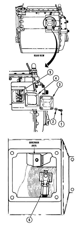
Using 1/2 inch socket, remove four bolts (1) and
washers (2) retaining LH brake adjusting cover (3).
Remove cover (3) and gasket (4).
Remove governor assembly (5), turning clockwise to
disengage gear teeth.
NOTE
Combination wrench turned to right
(counterclockwise rotation of adjusting
link) tightens brake.
Combination wrench turned to left (clock-
wise rotation of adjusting link) loosens
brake.
Using 11/16 inch 60° angle-head wrench, turn brake
adjusting link (6).
Alternately turn adjusting link (6) with angle-head
wrench and apply torque wrench at 40 lb-ft (54 N•m)
on shaft until indicator lines up opposite APPLY mark.
Install governor assembly (5), engaging gear counter-
clockwise.
Install cover (3) with new gasket (4).
Using 1/2 inch socket, install four bolts (1) and
washers (2) retaining cover.
Using torque wrench, tighten four bolts (1) to 17-20
lb-ft (23-27 N•m).
End of Task 2
Go to Sheet 4
5-6 Change 1
Para. 5-3, Task 2
|
|