TM 9-2815-202-34
(17)
(18)
Install four bolts (9) and four
Iockwashers (10). Tighten all bolts
alternately and evenly. Torque bolts
to 7-9 Ib-ft (10-12 N-m).
Rotate drive shaft (5) by hand. Shaft
should rotate freely. If not, gently tap
corner of fuel pump body (8) with
hammer to free up.
e. Installation
(1)
(2)
(3)
(4)
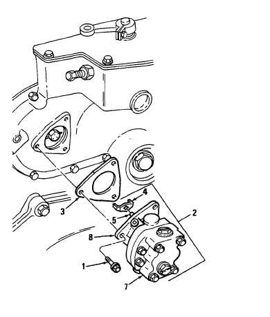
Install gasket (3) on fuel pump body
(8).
Install drive coupling fork (4) on
square end of drive shaft (5).
Position inlet opening on pump body
cover (7) (marked L.H. IN) facing
down.
Install fuel pump assembly (2) to
governor housing.
NOTE
Insure drive coupling fork (4) is
alined and contacts slots in the drive
disc.
(5) Install three bolts (1) securing fuel
pump assembly (2) to governor
housing. Torque bolts to 13-17 Ib-ft
(18-23 N-m).
END OF TASK
FOLLOW-ON MAINTENANCE
Para Description
4-8
Thermostat housing and crossover tubes installed (Except on 7083-7391, 7083-7396, and
7083-7399)
4-6
Fuel lines installed (7083-7395 and 7083-7398)
5-4
Fuel lines installed (7083-7396 and 7083-7399)
5.1-4 Fuel lines installed (7083-7391)
C h a n g e 1
4-45
|
|