|
|
|
|

|
TM 9-2815-202-34
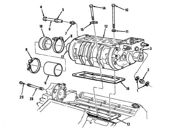
4-18. GOVERNOR AND BLOWER ASSEMBLY REMOVAL/lNSTALLATION (Cont)
(6)
(7)
(8)
(9)
(10)
Aline holes in new gasket (1 6). Place gasket (16) on engine block (1 3).
Position cover (18) in hose assembly (9). Install hose assembly (9) and two clamps (8) on
blower drive support (27).
Install oil tube fitting (7) on blower. Tighten securely.
Slide oil tube (6) with oil tube nuts (4 and 5) into oil tube fitting (7).
Position two hoses (2) and four clamps (1) on governor housing fuel rod tubes (3).
CAUTION
Lower blower assembly carefully onto block to avoid damaging or moving gasket.
NOTE
Attach sling to blower. Lift blower assembly at a slight angle. Lower blower on top of
cylinder block with flange of rear end plate cover inside of seal ring.
(11) Install two bolts (10) and two washers (11) securing blower (12) to block (1 3). Hand tighten.
NOTE
Lip on beveled end of retaining clip (15) goes in small recess in blower housing.
4-60
|
|
|
|
|
Privacy Statement -
Copyright Information. -
Contact Us