TM 9-2815-202-34
4-19. BLOWER DRIVE GEAR AND SUPPORT REPLACEMENT
This task covers:
a. Removal
b. Disassembly
c. -Cleaning/Inspection
d. Assembly
e. Installation
INITIAL SETUP
MODELS
EXPENDABLE/DURABLE SUPPLIES
ALL
Engine oil (App C, Item 16)
4 Bolts 3/8-24 x 4-1/2 (App C, Item 5)
Nut 3/8-24 (App C, Item 29)
Dry cleaning solvent (App C, Item 10)
TOOLS AND SPECIAL TOOLS
General mechanics tool kit (App B, Item 96)
EQUIPMENT CONDITION
.
Dial indicator (App B, Item 44)
Micrometer (1-2") (App B, Item 65)
Vernier caliper (App B, Item 10)
Torque wrench (App B, Item 101)
MANDATORY REPLACEMENT PARTS
Para Description
4-15 Breather removed
4-16 Blower drive shaft and hub removed
(7083-7395 and 7083-7398)
n
4-18 Blower removed
5-15 Blower drive shaft and hub removed
(7083-7391, 7083-7396, and 7083-7399)
1 Gasket (App F, Item 69)
1 Key washer (App F, Item 167)
2 Copper washers (App F, Item 163)
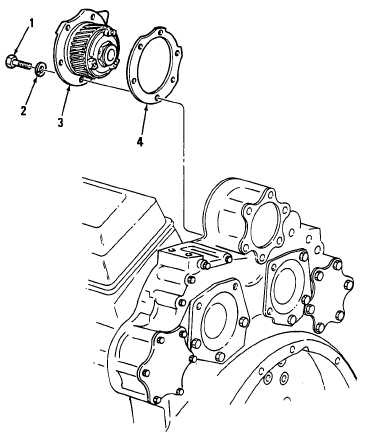
a. Removal
(1) Remove two bolts (1) and two copper
washers (2) securing blower drive
support assembly (3) to rear end
plate. Discard copper washers.
(2) Remove blower drive gear support
assembly (3) and gasket (4) from rear
end plate. Discard gasket.
b. Disassembly
(1)
(2)
(3)
Clamp blower drive gear support
assembly (3) in a soft-jawed vise with
blower drive gear (5) on top.
Straighten tangs on key washer (6).
Remove nut (7). Discard key washer.
Remove thrust washer (8), thrust
bearing (9), gear (5), and thrust
bearing (10) from gear support (11).
4 - 6 2
Change 1
|
|


