d.
TM9-2815-202-34
(3) Inspect four helical gears, two oil pump gears, and spur gear for chipped teeth, burrs, wear,
or damage.
(4) Inspect drive and driven shaft for scoring, wear, or damage.
(5) Inspect bushings in oil pump housing and scavenger pump housing for wear, If worn,
replace oil pump housing and scavenger pump housing.
(6) inspect strainer element screens for cracks, tears, or damage.
(7) Inspect tube assembly and adaptor for cracks or damage.
(8) Inspect studs for continuity or damage to threads.
Assembly
DRIVEN
SHAFT
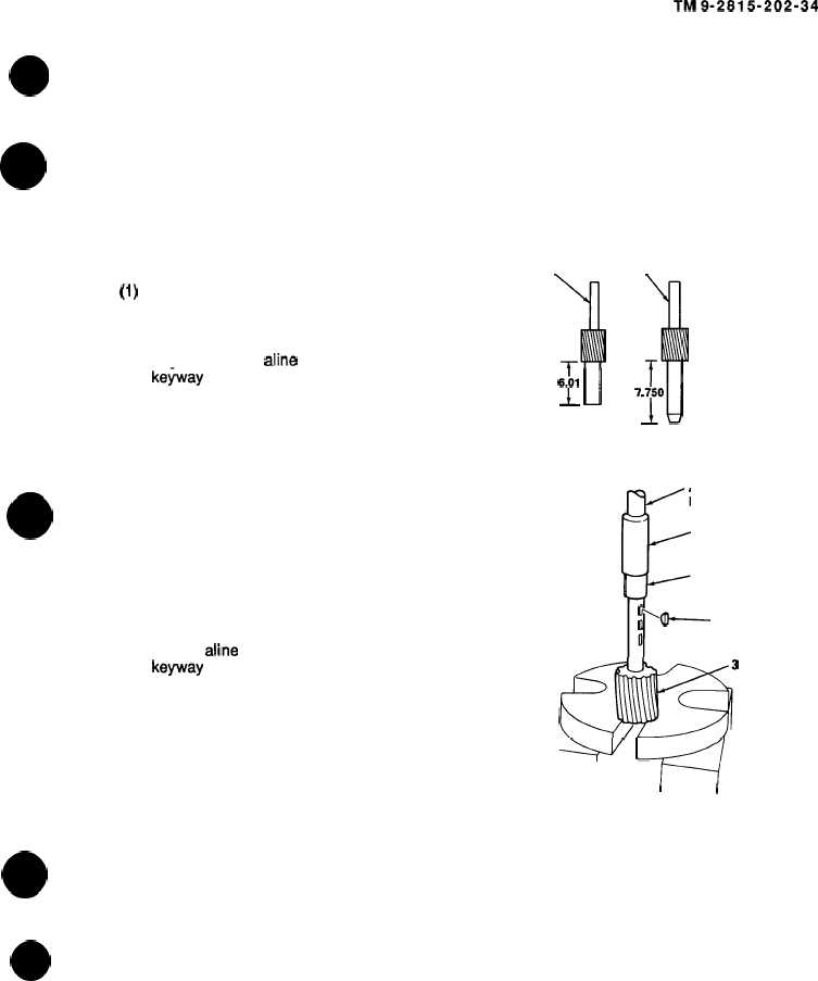
(1)
(2)
(3)
(4)
(5)
Insert woodruff key (42) into driven
shaft (36).
Lubricate driven shaft (36) with
engine oil, and aline helical gear (38)
1
ke~ay with woodruff key (42) on
driven shaft.
6!01
J- U
NOTE
Position of helical gear should be
6.01 inch from end of driven shaft.
Using driven gear installer (48) and
arbor press, install helical gear (38)
onto driven shaft (36).
Insert woodruff key (41 ) into drive
shaft (34).
Lubricate drive shaft (34) with engine
oil and aline oil pump gear (39)
keyway with woodruff key (41) on
drive shaft.
NOTE
DRIVE
SHAFT
3
T
7.i50
dl
ARBOR
F
PRESS
48
34,36
0
‘+ 41,42
0
6,39
Position of oil pump gear should be
+ WI
7.750 inch from end of drive shaft.
I
(6)
(7)
(8)
(9)
I
I
Using drive gear installer (48) and
arbor press, install oil pump gear (39)
onto drive shaft (34).
Install drive shaft (34) and oil pump gear (39) as an assembly into oil pump housing (32).
Install driven shaft (36) and helical gear (38) as an assembly into oil pump housing (32).
Place oil pump housing (32) in a soft-jawed vise and place a rag between oil pump gear (39)
and helical gear (38).
4 - 1 27
|
|