TM 9-2815-202-34
1-8. LOCATION AND DESCRIPTION OF COMPONENTS (Cont)
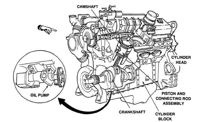
s. Cylinder Heads. Mounted on the top of each cylinder bank. They contain fuel manifolds,
exhaust valves, injectors, injector and valve operating mechanisms, and glow plugs (model
7083-7391 ). Special Low Heat Rejection (LHR) cylinder heads are used on model 7083-7391. These
heads reject less heat to the coolant; therefore, more heat energy in the exhaust gases is available for
use by the turbocharger. Built in heat shields in the exhaust ports, which insulate hot exhaust gas from
the engine coolant, are the main feature of the LHR cylinder head.
t. Camshafts. Located on top of each cylinder bank. They actuate injector and exhaust valve
operating mechanisms.
u. Cylinder Block. Being the main structural part. It provides rigidity and ensures alinement of all
load bearing assemblies.
v. Crankshaft. Attached to the bottom of the cylinder block. It transfers the engine load through the
flywheel and supplies oil to piston assemblies.
w. Piston and Connecting Rod Assemblies. Four assemblies are located in each bank. Pistons
are cooled and lubricated by oil pressure fed up through drilled connecting rods.
x. Oil Pump. Mounted on the bottom of the cylinder block. It pumps oil throughout the engine for
lubrication and cooling.
1-8
Change 1
|
|


