TM 9-2815-202-34
4-38. CYLINDER HEAD REPAIR (Cont)
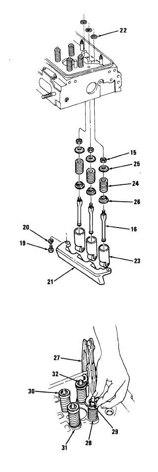
(8) Rest cylinder head on its side and
remove eight cam follower guide bolts
(19), eight Iockwashers (20), and four
cam follower guides (21). Discard
lockwashers.
(9) Remove twelve cam follower spring
retainers (22) from cam follower bores
in cylinder head.
(10) Pull twelve cam followers (23) and
twelve push rods (16) assemblies
from bottom of cylinder head. Remove
twelve push rod nuts (15), twelve
upper spring seats (25), twelve cam
follower springs (24), and twelve
lower spring seats (26) from twelve
push rods.
NOTE
Mark location of valve for
reinstallation. With used valves,
valves must go back in original
location.
(11) Remove sixteen exhaust valves as
follows:
(a) Position cylinder head on its side.
(b) Using valve spring compressor
(27), compress valve spring (28).
Remove two-piece tapered valve
locks (29).
(c) Remove upper spring seat (30),
valve spring (28), lower spring
seat (31) , and exhaust valve (32).
NOTE
•l Model 7083-7395 contains four
bolts (33), four flat washers (34),
two cover plates (35), and two
gaskets (36) per head.
• Model 7083-7398 contains six
bolts, six flat washers, three cover
plates, and three gaskets per
head.
4-186
|
|