TM 9-2815-202-34
4-41. BLOWER
d. Assembly
REPAIR (Cont)
NOTE
Dowel pins must project 0.320 inch
(8.23 mm) from flat face of front end
plate to assure proper alinement of
end plate with housing.
(1)
(2)
(3)
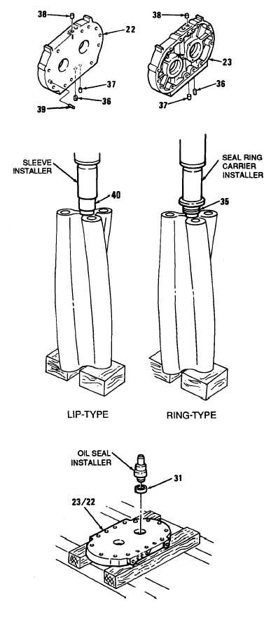
If removed, install two dowel pins (39)
in each end plate (22 or 23). Pins
must project 0.320 inch (8.23 mm)
above face of plate.
If removed, install two oil strainers
(36) and two sleeve bushings (37) in
bottom of end plates (22 and 23).
Strainer must be flush to 0.015 inch
(0.38 mm) below surface.
Install two plugs (38) in top of end
plates (22 and 23).
NOTE
Steps (4) thru (6) provide
information to install oversized
replacement lip-type oil seals on
rotor shafts and end plates. If the
ring-type oil seals, carriers, and
collars are still available from
existing stock, proceed to steps (9)
thru (16).
(4)
(5)
(6)
(7)
(8)
4-240
Support blower rear end plate (22),
finished surface facing up, on two
wooden blocks.
Start oil seal (31 ) straight into bore of
end plate with part number facing up
(away from bore).
Place short end of oil seal installer in
oil seal (31 ). Tap oil seal into end
plate (22) until shoulder of installer
contacts end plate.
To install remaining oil seals (31) in
end plates (22 and 23), repeat steps
(4) thru (6).
Position rotor on two wood blocks
under arbor press. Using oversized
seal pilot, press oil seal sleeves (40)
on rotor shaft until sleeve contacts
rotor.
|
|