TM 9-2815-202-34
NOTE
(23)
(24)
(25)
Mating surfaces between blower end plates and blower housing must be flat and
smooth. No gasket is used.
Apply light coating of Form A Gasket sealant to mating surfaces of end plate and blower
housing. Sealant must not protrude into housing.
Aline match marks on rear end plate (22) and blower housing (29). Install rear end plate with
flat finished surface towards blower housing. Slide end plate down over oil seal pilots. Aline
dowel pins (39) with holes in blower housing. Push end plate against blower housing. If
installed, remove oil seal pilots.
Install two screws (28) through rear end plate (22) into blower housing (29). Invert blower
housing and install two screws through front end plate (23). Torque screws to 5-10 Ib-ft
(7-14 N-m).
CAUTION
Check relationship of blower end plates to blower housing on the bottom face.
Protrusion must not be more than 0.0005 above or 0.0065 inch below end plate.
Excessive protrusion could distort blower housing when end plate mounting bolts are
tightened and could cause rotor to housing contact.
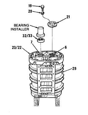
(26) Lubricate rear ball bearings (32) with light engine oil. Position two bearings, numbered end
up, on rear end plate (22) and straight on shafts of rotors (6 and 7).
(27) Place seal and rear bearing installer on top of rear ball bearings (32). Tap bearings straight
and onto shafts of rotors (6 and 7) into rear end plate (22).
NOTE
Position retainer with word “OUT”
away from end plate.
(28)
(29)
Position two bearing retainers (21) on
rear end pIate (22). Install six bolts
(19) and six Iockwashers (20). Torque
bolts to 7-9 Ib-ft (9-12 N-m).
Invert blower housing (29). To install
two front roller bearings (32) and two
retainers (21) on front end plate (23),
repeat steps (24) thru (26) using front
bearing installer.
Place blower housing (29) in upright
position with gear end up on two
wood blocks.
NOTE
Rotors must turn freely for proper
assembly.
4-243
|
|


