TM 9-2815-202-34
5-41. GOVERNOR REPAIR (Cont)
(48)
(49)
(50)
(51)
(52)
(53)
(54)
(55)
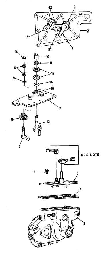
Lubricate inside of two bushings (16)
with grease.
Place stop lever return spring (8) over
boss on inner face of governor cover
(2).
Insert stop lever shaft (7) part way
through hole in governor cover (2)
and hook end of return spring (8) over
end of lever. Push shaft up in cover.
Position stop lever (7) against stop
pin (91 ), opposite spring (8).
Install seal ring (9), two washers (6),
and retaining ring (5) securing stop
lever to governor cover (2).
Install speed control shaft (13) into
governor cover (2) between two pins
(92).
Install seal ring (14), two washers
(12), and retaining ring (11) securing
speed control shaft to governor cover
(2).
Install spacer (10) on speed control
shaft (13).
NOTE
If remote control levers were
removed during disassembly of
governor cover, reinstall levers.
(56) Install governor cover (2) and gasket
(4) on governor (3). Secure with eight
screws (1) and tighten screws.
END OF TASK
FOLLOW-ON MAINTENANCE
Para Description
5-17 Install governor on blower
5-42. WATER PUMP REPAIR
(See para 4-43)
5-74
|
|