TM 9-2815-202-34
14
l
l
IGHT BANK
FRONT
l
*
14
#
(6]
(7)
&
(8)
LEFT
RE
14
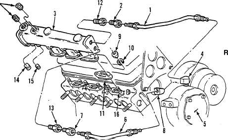
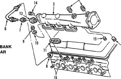
if removed, install two fittings (7 and 13), four plugs (14) and plug (15) in left water manifold (3).
Repeat steps (2) and (3) above for left water manifold.
Connect tube assembly (6) at elbow fitting (8) on front of cylinder head and at lower fitting (7)
on left water manifold (3). Tighten connections.
END OF TASK
FOLLOW-ON MAINTENANCE
Para Description
e
8 Install glow plug harness clips
Install exhaust manifolds
2 Install turbocharger
3-14 Install air inlet manifold
3-7 Install oil level gauge rod
@. WATER PUMP REMOVAIJINSTALLATION
(See Para 5-7)
Change 1
5-83
5.1-7
|
|


