TM9-2815-202-34
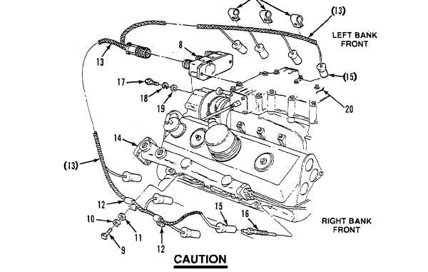
(10) Remove two bolts (17), two Iockwashers (18), two flat washers (19), and glow plug controller
(8) from rear of air inlet housing (20). Discard Iockwashers.
b. Installation
(1)
(2)
(3)
(4)
(5)
(6)
(7)
(8)
Secure glow plug controller (8) to rear of air inlet housing (20) with two flat washers (1 9), two
Iockwashers (18), and two bolts (17). Torque bolts to 84-108 lb-in (9-12 N-m).
If removed, install three clips (12) on left side or two clips on right side of glow plug harness
(13).
Attach plug connection end of glow plug harness (13) to rear right side connector on glow plug
controller (8). Tighten securely.
Install four glow plugs (16) in left cylinder head. Torque glow plugs to 11-13 Ib-ft (15-18 N-m).
Glow plug harness leads are identified with location near ends of wires. Correct
installation of wires is necessary for proper diagnostics to aid in locating a failed glow
plug.
Install four plug ends (15) of glow plug harness (13) to corresponding glow plug (16) locations
in cylinder head.
Attach glow plug harness (13) to left side water manifold (14) by securing three clips (12) with
three flat washers (11), three Iockwashers (10), and three bolts (9). Torque bolts to 13-17 Ib-ft
(18-23 N-m).
Attach glow plug harness (13) to right side water manifold (14) by securing two clips (12) with
two flat washers (11 ), two Iockwashers (10), and two bolts (9). Torque bolts to 13-17 Ib-ft
(18-23 N-m).
Repeat steps (4) and (5) above for opposite side.
Change 1
5-85
|
|