TABLE 6-2
TM9-2815-202-34
6-34. PISTON AND CONNECTING ROD MAINTENANCE (TRUNK TYPE) (Cont)
•
•
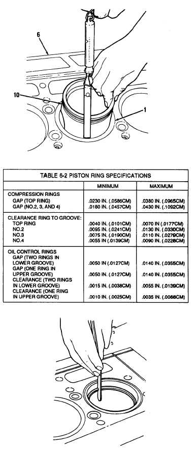
(2)
(3)
NOTE
Use feeler gage to check piston to
liner clearance. Use a spring scale
attached to feeler gage to measure
amount of force in pounds required
to withdraw feeler gage from
between piston and liner. Select
feeler gage with thickness requiring
six pounds pull to move. Piston to
liner clearance is 0.001 inch greater
than thickness of feeler gage used.
For example, a 0.004 inch feeler
gage indicates 0.005 inch clearance
when withdrawn with a six pound
pull.
Feeler gage must be perfectly flat
and free of nicks and bends.
With cylinder liner (1) installed in
cylinder block (6), hold piston (10)
upside down in liner and measure
clearance in four places, 90 degrees
apart. Clearance must be 0.0045 to
0.0083 inch with new parts. Allow a
maximum clearance of 0.0120 inch
for used parts.
If binding occurs between piston and
liner, remove piston and examine
piston and liner for burrs. Remove
burrs on piston with a fine stone.
Remove burrs in liner with fine flat
hone and recheck clearance.
f. Fitting Piston Rings
(1) Insert ring inside cylinder liner in
normal area of ring travel. Using
piston to push ring down, measure
ring gap with feeler gage. Refer to
Table 6-2 for ring gap specifications.
Repeat procedure for balance of
compression and oil rings.
File or stone both ends of
compression ring from outer surface
to inner surface to prevent chipping
or peeling of chrome plating on ring.
(2) File ends of compression ring if ring
gap is too small. Ends of ring must
remain square, and chamfer on outer
edge must be approximately 0.015
inch.
6-36
|
|