TM9-2815-202-34
(7)
(8)
(9)
(10)
(11)
To check bearing to crankshaft
journal clearance, place a plastic
gage strip (28) between crankshaft
journal (26) and connecting rod cap
(3). Tighten connecting rod nuts (2) to
60-70 Ib-ft (81-95 N-m). Remove
connecting rod nuts and cap, and
measure width of plastic gage with
measuring strip (29). Maximum
clearance with used parts is 0.0056
inch.
Lubricate bearing with clean engine
oil and install bearing cap (3) and
lower bearing shell (4) on connecting
rod (5) with identification numbers on
cap and rod adjacent to each other.
Install two connecting rod bolt nuts (2)
and torque to 60-70 lb-ft (81-95 N-m).
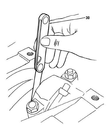
NOTE
If necessary, pry connecting rods
apart before measuring side
clearance.
Using feeler gage (30), measure side
clearance between each pair of
connecting rods. Clearance limits are
0.008 to 0.016 inch.
Repeat steps (1) thru (9) to install
additional liners, pistons, and rod
assemblies. Use hold-down clamps to
hold each installed liner in place.
Remove all liner hold down clamps.
END OF TASK
FOLLOW-ON MAINTENANCE
Para
6-33
6-32
6-28
6-21
6-35.
6-36.
6-37.
Description
Install oil pump
Install oil pressure regulator and relief
valve
Install cylinder head
Install oil pan
CYLINDER LINER MAINTENANCE
CRANKSHAFT MAINTENANCE
CYLINDER BLOCK MAINTENANCE
(See Para 4-34)
(See Para 4-35)
(See Para 4-36)
6-43
|
|