TM 9-2815 -202-34
(32)
(33)
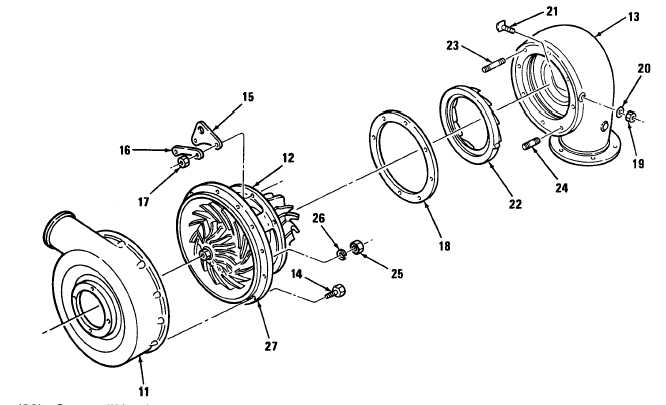
Secure lifting bracket (15) and turbine housing (13) to center housing assembly (12) with
four locking plates (16) and eight nuts (17). Torque nuts to 20-25 Ib-ft (34-41 N-m).
Adjust turbine housing to turbine wheel clearance as follows:
(a) Place turbine housing (13) flat on bench resting on exhaust flange.
NOTE
When turning rotor assembly during adjustment, turbine should rub just lightly enough
to hear a soft contact noise but not heavy enough to feel any binding.
(b)
(c)
(d)
(e)
Check impeller (32) for free spin. Rotor assembly (31 ) should rub lightly on turbine
housing (13).
NOTE
Turbine housing shims come in 0.010 and 0.042 inch thicknesses.
If turbine wheel does not rub lightly on turbine housing (13), remove housing and add or
remove shims (18) until light rubbing is achieved.
Remove turbine housing (13) from center housing assembly (12). Add shims (18) to
provide an additional clearance of 0.019 to 0.029 inch.
Reinstall turbine housing according to steps (30) thru (32).
(34) Bend four locking plates (16) over sides of eight nuts (17).
6-53
|
|