
| Tweet |

Custom Search
|
|

|
||
 TM 9-2815-220-24
INTAKE AND EXHAUST VALVE CLEARANCE ADJUSTMENT
0034 00
ADJUSTMENT (Continued)
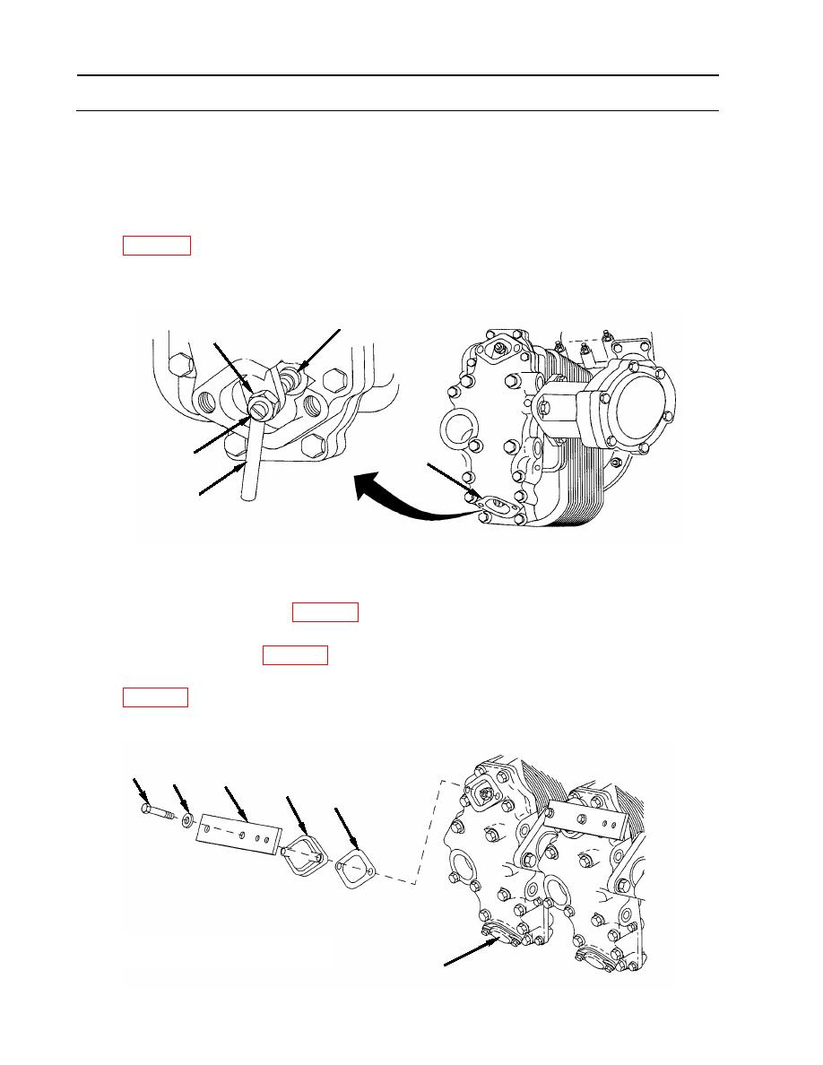
2. Adjust intake valve (7) clearance (0.010 inch, 0.254 mm).
a. Loosen intake valve adjusting screw lock nut (13).
b. Turn valve adjusting screw (14) until clearance between valve adjusting screw pad (15)
and valve stem is 0.010 inch (0.254 mm) using thickness gauge blade (16) (item 55,
c. Torque lock nut (13) to 200-225 inch-pounds (23-25 Nm) after correct adjustment is
made. Make certain setting has not changed after tightening lock nut (13).
15
13
14
7
16
AFTER ADJUSTMENT
1. Install upper and lower access covers (1).
a. Apply Lubriplate (item 23, WP 0173) to threads of four screws (2) prior to installation.
b. Install access cover (1) with spacer plate (4) on exhaust side of valve cover using new
gasket (5) (item 350, WP 0175), two screws (2), and two flat washers (3).
c. Install access cover (1) on intake side of valve cover, using new gasket (5) (item 350,
d. Torque four screws (2) to 150-175 inch-pounds (17-20 Nm).
2
3
4
1
5
END OF WORK PACKAGE
1
WP 0034 00-4
|
||
|
||


