
| Tweet |

Custom Search
|
|

|
||
 TM 9-2815-220-24
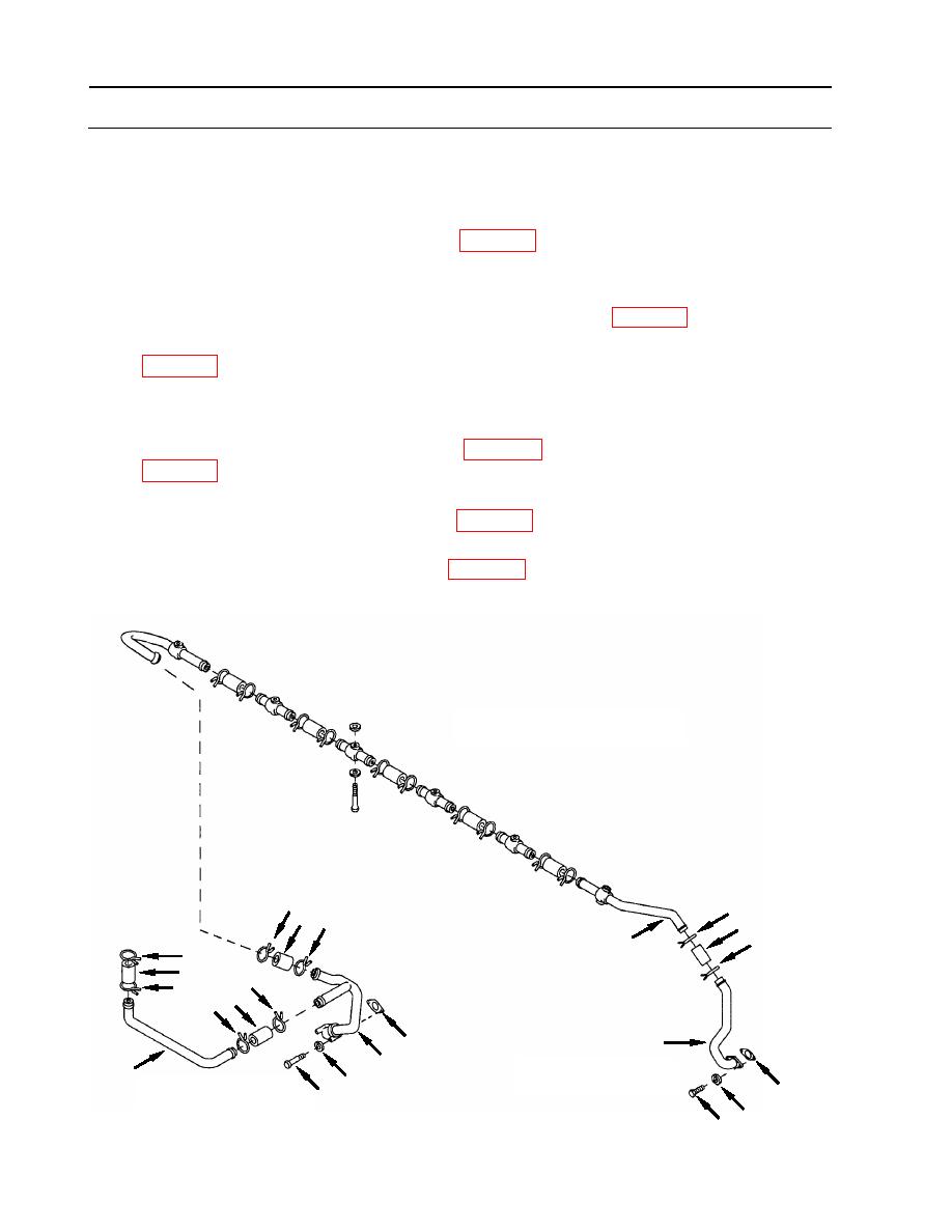
CYLINDER OIL DRAIN TUBES REPLACEMENT
0077 00
INSTALLATION (Continued)
3. Install [left bank damper end] oil drain tube (37).
a. Position clamp (40) onto tube (37) far enough towards flange end to be out of the way.
b. Install new lubricated hose (41) (item 313, WP 0175) half way onto tube and secure with
clamp (40).
c. Place a clamp (40) on tube (50) and push hose (41) with tube (37) onto tube (50).
d. Install tube (37) to oil pan, using a new gasket (42) (item 159, WP 0175).
e. Secure tube (37) to oil pan using two screws (38) with new lock washers (39) (item 93,
4. Assemble tube (34) to tube (26).
a. Position clamps (31) over ends of tubes (34, 26) and slide clamps out of the way.
b. Using new, lubricated hose (32) (item 313, WP 0175) (using lubricating oil, item 21,
clamps yet.
c. Push new, lubricated, hose (30) (item 313, WP 0175) half way onto tube (26) and secure
with clamp (29).
d. Push new lubricated hose (36) (item 313, WP 0175) onto end of tube (34) and secure with
clamp (35).
LEFT BANK OIL DRAIN
29
40
30 29
41
40
50
35
36
35 32 1
3
31
37
33
26
DAMPER END
34
28
42
FLYWHEEL END
27
39
38
WP 0077 00-8
|
||
|
||


