
| Tweet |

Custom Search
|
|

|
||
 TM 9-2815-220-24
FUEL/WATER SEPARATOR REPAIR/FILTER ELEMENT REPLACEMENT
0085 00
ASSEMBLY
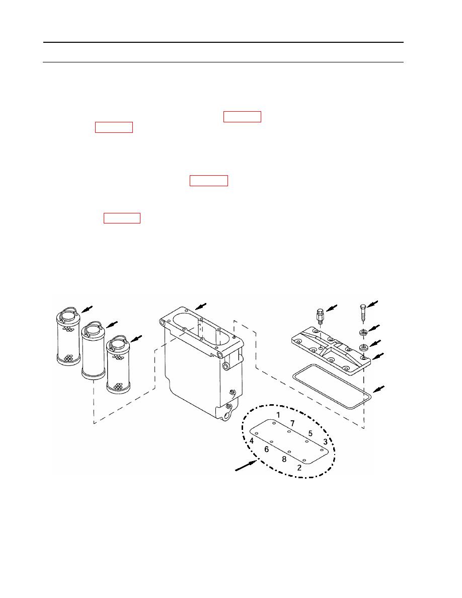
1. Install bleeder valve (2) in cover (23).
2. Install two new outer elements (25) (item 196, WP 0175) and new inner element (26)
(item 195, WP 0175).
3. Install cover (23).
a. Place new gasket (24) (item 197, WP 0175) in position.
b. Install cover (23) and secure using eight screws (20), with new lock washers (21)
(item 92, WP 0175) and flat washers (22).
c. Torque screws to 144 inch-pounds (16.27 Nm) in accordance with torque sequence
diagram.
20
4
2
25
26
21
25
22
23
24
TORQUE SEQUENCE DIAGRAM
WP 0085 00-6
|
||
|
||


