
| Tweet |

Custom Search
|
|

|
||
 TM 9-2815-220-24
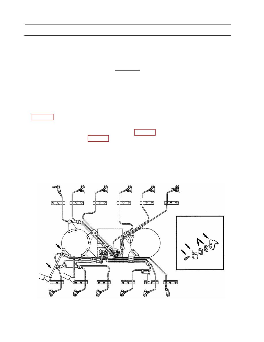
FUEL INJECTION TUBES REPLACEMENT
0113 00
INSTALLATION (Continued)
8. Install inner fairlead half (28) between tube assembly and angle bracket (31) (see detail C).
CAUTION
When bending injection tubes is required, be careful not to nick
tubing. The bending tools are designed to allow bending without
nicks.
9. Assure that fairlead half (28) is aligned with bracket (31) holes and align tube to fit within
1/8 inch (3.175 mm) in any direction with fairlead half. Use two bending tools (24) (item 13,
10. Install outer fairlead half (28) (see detail C).
a. Apply a small amount of Lubriplate (item 23, WP 0173) to threads of two new self-locking
screws (32) (item 223, WP 0175).
b. Install retainer (30) using two screws (32) to secure to angle bracket (31).
c. Tighten two screws (32) to 160-180 inch-pounds (18-20 Nm).
C
31
28
30
C
32
24
WP 0113 00-8
|
||
|
||


