
| Tweet |

Custom Search
|
|

|
||
 TM 9-2815-220-24
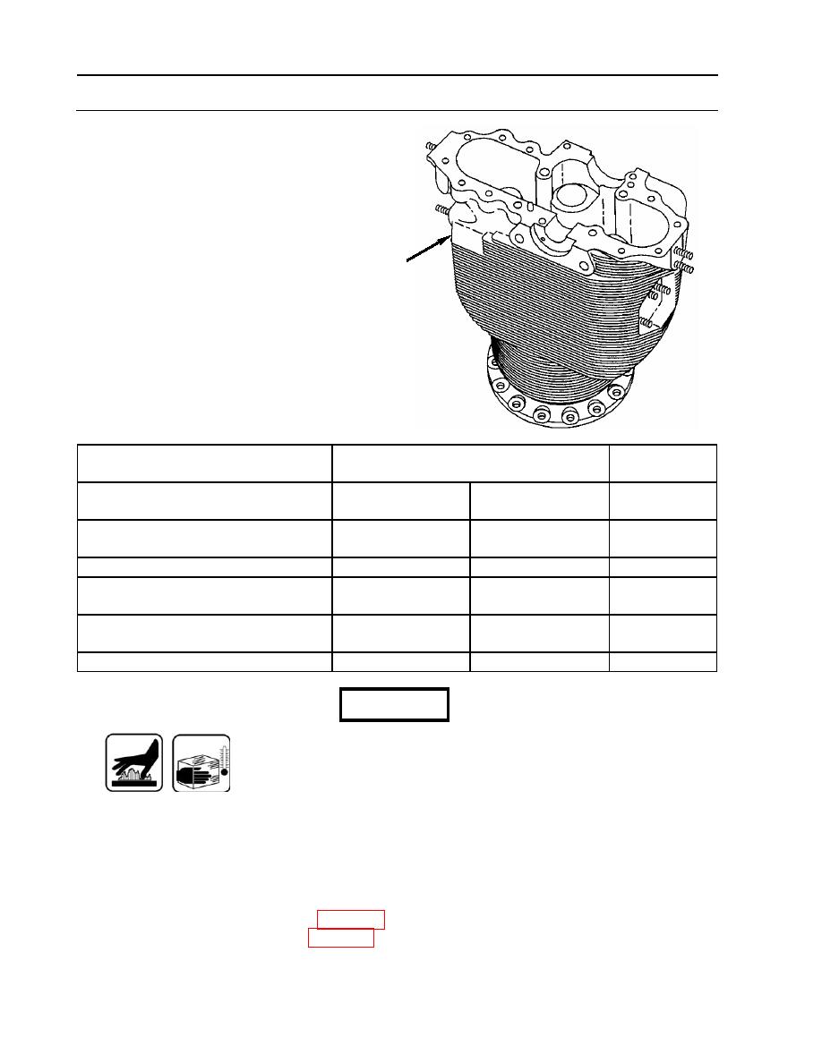
CYLINDER ASSEMBLY REPAIR
0135 00
REPAIR (Continued)
3. Check valve guide bores in cylinder
assembly (1). If not within the following
limits, cylinder assembly (1) must be
replaced.
1
Point of Measurement
Size and Fit of New Parts
Wear Limits
inches (mm)
Outside diameter of intake valve
0.6890 (17.5006)
0.6895 (17.5133)
None
guide
Inside diameter of intake valve guide
0.6870 (17.4498)
0.6880 (17.4752)
None
bore in cylinder head
Fit of intake valve guide in bore
0.0010T (0.0254)
0.0025T (0.0635)
None
Outside diameter of exhaust valve
0.7525 (19.1135)
0.7530 (19.1262)
None
guide
Inside diameter of exhaust valve
0.7495 (19.0373)
0.7505 (19.0627)
None
guide bore in cylinder
Fit of exhaust valve guide in bore
0.0020T (0.0508)
0.0035T (0.0889)
None
WARNING
Wear gloves when handling heated or chilled parts.
4. Heat cylinder assembly to 350 F (176 C) maximum and chill valve guides for 1 hour
minimum in dry ice or 3 hours minimum at -40 F (-40 C) before installing.
NOTE
The intake and exhaust valve guides are installed in the cylinder in
the same manner. A separate replacer is used for each. Replacer
10883052 (item 100, WP 0176) is used for intake valve guides, and
10883053 (item 99, WP 0176) is used for exhaust.
WP 0135 00-12
|
||
|
||


