
| Tweet |

Custom Search
|
|

|
||
 TM 9-2815-220-24
CRANKSHAFT DAMPER REPAIR
0140 00
REMOVAL (Continued)
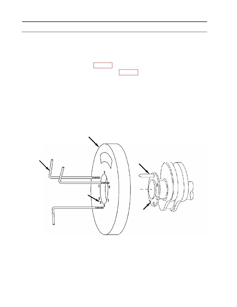
1. Remove vibration damper.
a. Position crankshaft and damper (1) so that one mounting bolthole is at the 12 o'clock
position and dowel pin (2) hole (A) is at approximately the 7 o'clock position.
b. Insert tapered bolt (3) (item 16 WP 0177) in bolt hole at the 12 o'clock position.
c. Install three mechanical pullers (4) (item 77, WP 0170) into screw holes provided in
vibration damper (1).
d. Alternately tighten pullers (4) to pull damper (1) from dowel pin (2) in flange of crankshaft
just until damper (1) is free of dowel (2) in crankshaft flange and resting on tapered
bolt (3).
e. Remove mechanical pullers (4).
f. Insert lifting strap through center of damper (1) and attach to suitable lifting device.
g. Lift just enough to relieve load on tapered bolt (3) and slide damper (1) free of bolt.
1
4
3
A
2
WP 0140 00-2
|
||
|
||


