
| Tweet |

Custom Search
|
|

|
||
 TM 9-2815-220-24
OIL PUMP REPAIR
0154 00
ASSEMBLY (Continued)
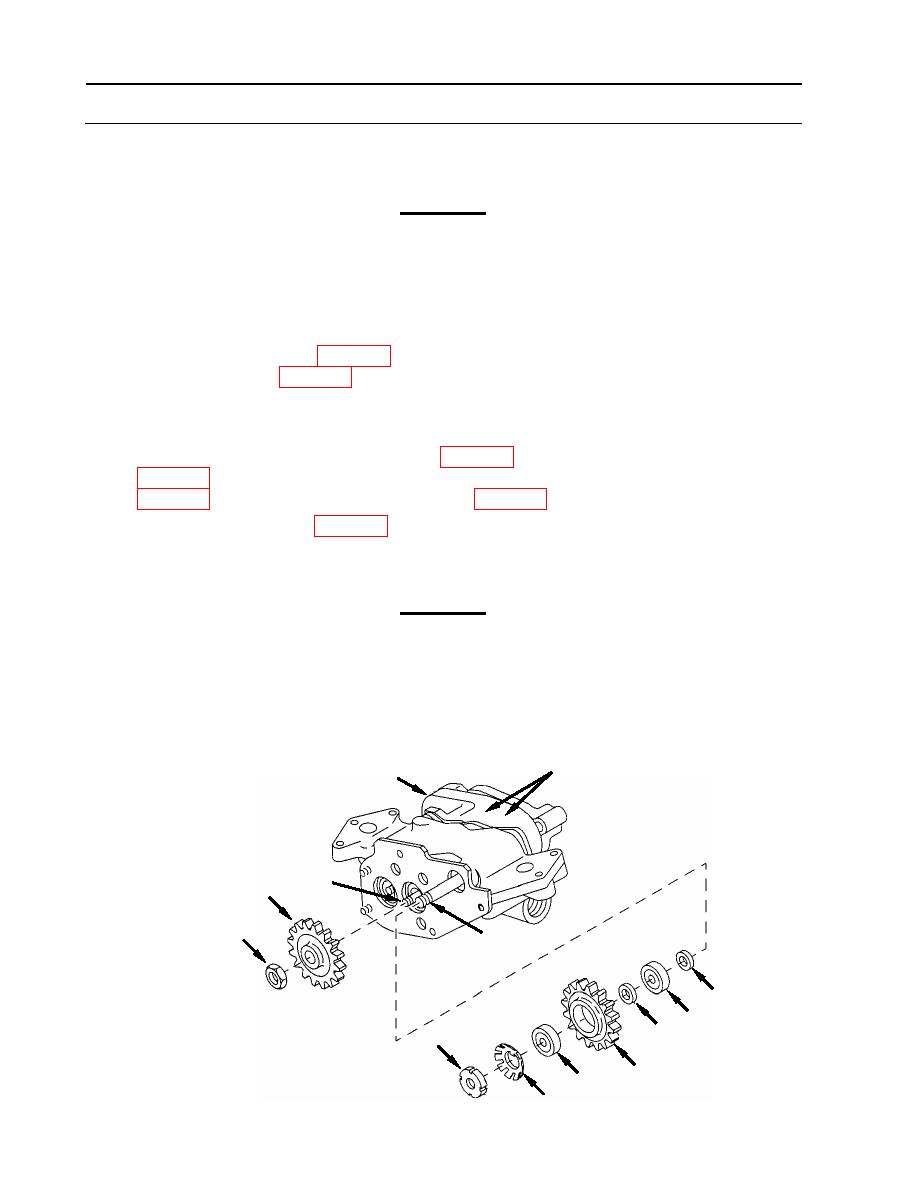
14. Position plate (13) onto cover assembly (27).
CAUTION
Do not insert brass rod or drift between impeller and housing. Damage to
housing may occur.
15. Install spur gear (22) on shaft (43).
a. Position a brass rod or drift between impellers (23 and 24) through opening in housing
assembly (25) to hold gear shaft (43) stationary.
b. Apply lubricant (item 23, WP 0173) to threads of shaft (43) and install new self-locking
nut (26) (item 219, WP 0173).
c. Torque self-locking nut (26) to 58-65 foot-pounds (79-88 Nm).
16. Install cluster gear (15).
a. Install new thrust bearing (21) (item 246, WP 0175), new ball bearing (19) (item 291.1,
b. Apply lubricant (item 23, WP 0173) to threads of shaft (18) and install nut (17).
c. Torque nut (17) to 48-52 foot-pounds (65-71 Nm).
d. Bend tabs of key washer (16) to secure nut (17).
CAUTION
Force required to rotate pump gearing must not exceed 4 inch-pounds
(0.452 Nm). Damage to pump or premature failure may occur.
17. Check rotation force of pump gearing.
a. Place torque wrench on nut (17).
b. Rotate shaft. If more than 4 inch-pounds (0.452 Nm) are required to turn shaft,
investigate cause of binding.
23, 24 (hidden)
25
43
22
26
18
21
19
20
17
15
19
16
WP 0154 00-16
|
||
|
||


