| Tweet |

Custom Search
|
|

|
||
 TM 9-2815-220-24
OIL PUMP REPAIR
0154 00
ASSEMBLY (Continued)
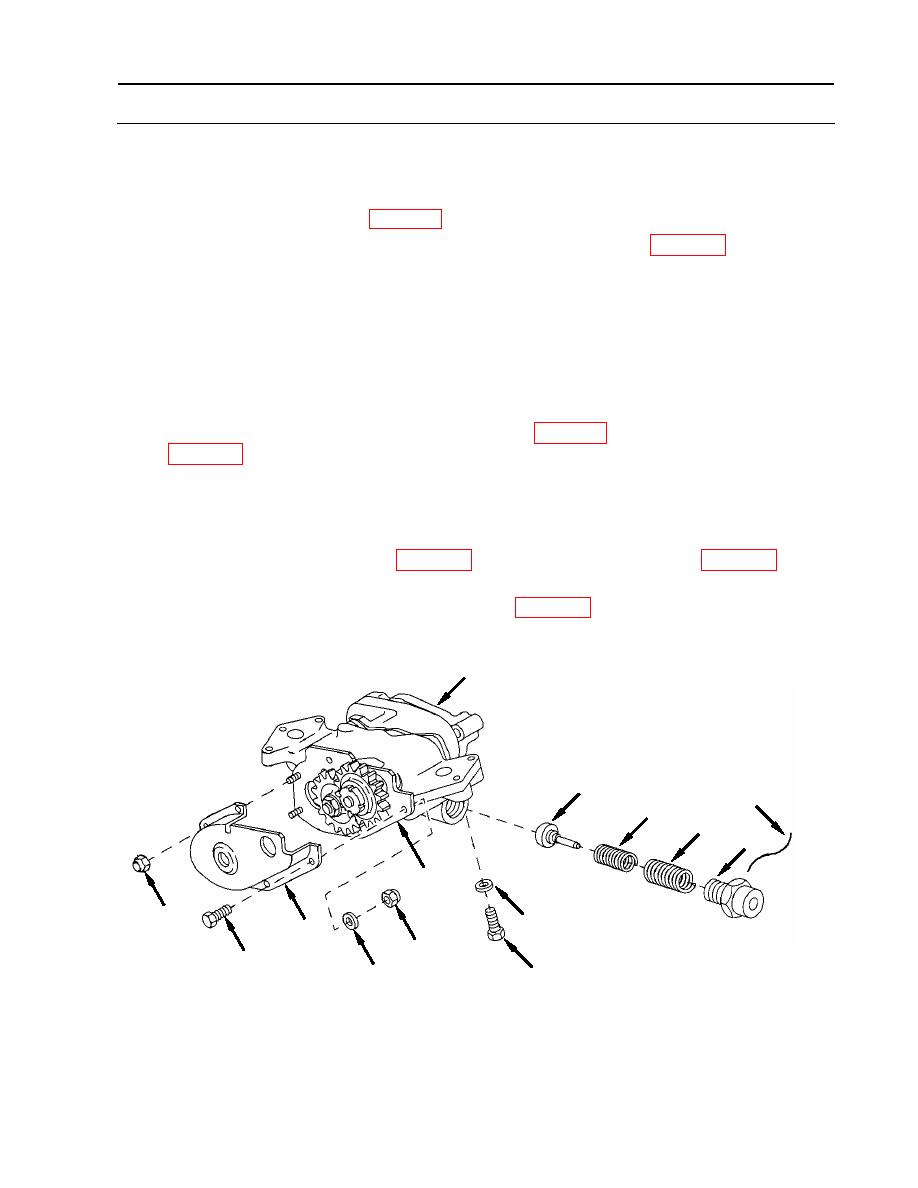
18. Install gear cover (8).
a. Secure to gear plate (14) using three screws (13) with flat washers (12), and new self-
locking nuts (11) (item 33, WP 0175).
b. Secure to pump (10) using two new self-locking nuts (9) (item 33, WP 0175).
c. Torque self-locking nuts to 125-150 inch-pounds (14-17 Nm).
NOTE
Mounting screw (6) cannot be installed in pump after relief valve is
installed.
19. Place screw (6) and flat washer (7) into housing assembly (28).
20. Install relief valve (5).
a. Install valve (5), new inner spring (4) (item 287.1, WP 0175), outer spring (3) (item 346.1,
NOTE
Temporarily install oil pump assembly on engine, if available, to
torque cap.
b. Using modified socket (item 12, WP 0177) and torque wrench (item 124, WP 0176),
torque cap (1) to 150-170 inch-pounds (17-19 Nm).
c. Secure cap (1) with new lock wire (2) (item 23, WP 0173).
10
5
2
4
3
1
14
9
7
8
11
13
6
12
END OF WORK PACKAGE
WP 0154 00-17 (18 blank)
|
||
 |
||