TM 9-2815-225-34&P
3-59. FUEL GEAR PUMP REPAIR (Contd)
LOCATION/ITEM
ACTION
REMARKS
e. Assembly
NOTE
Prior to assembly, place gear cover and gear body on bench.
13. Four bearing sleeves (15)
Install on gear cover (9) and gear
Perform this step only if bearing
and dowel ring (8)
body (13).
sleeves (15) and dowel ring (8)
were removed from gear body (13)
and gear cover (9).
14. Pipe plug (14)
Install on gear body (13).
Tighten plug (14) to 10-13 lb-ft
(14-18 Nm).
15. Two gears (11)
Press on idler shaft (12) and drive
Perform this step only if gear was
shaft (17) 0.680-0.690 in. (17.272-
removed from shaft. Repeat this
17.526 mm) away from gear
step for each gear.
body end of shaft.
16. Pressure valve (18)
Using pressurizing valve driver,
Use pressurizing valve driver
install on gear cover (9).
(3375959). Pressure valve must be
even to 0.015 in. (0.381 mm) below
face of gear cover (9). If valve is
damaged at all during installation,
replace with new valve.
NOTE
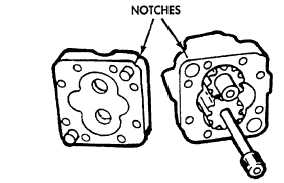
Location of notches or ridges and drive shaft determine pump rotation.
When a right-hand rotation pump is being assembled, place driven gear shaft of gear
pump in pocket nearest locating notches or ridges. Place driving gear shaft in other
pocket. The dowel ring is always located around drive shaft.
17. Idler shaft (12), drive shaft
Lubricate and install on gear
Ensure all parts are clean.
(17), and two gears (11)
body (13).
18. Gear cover (9) and new
a. Install on gear body (13).
Ensure location notches are
gasket(16)
aligned.
b. Install two screws (5), washers (6),
and new lockwashers (3).
NOTE
Drive shaft must protrude 2.370-2A12 in. (60.198-61.265 mm) from gear body. End clearance
should not exceed 0.0015 in. (0.0381 mm), nor be less than 0.0009 in. (0.0228 mm). Gaskets
are available in 0.0020 and 0.0015 in. (0.0509 mm and 0.0381 mm). If pump binds, has
excessive play or gear backlash, check for error in assembly which must be corrected to
prevent early pump failure. Total gear backlash must be 0.001-0.004 in. (0.0254-0.1016 mm).
3-402
|
|


