TM 9-2815-225-34&P
3-79.
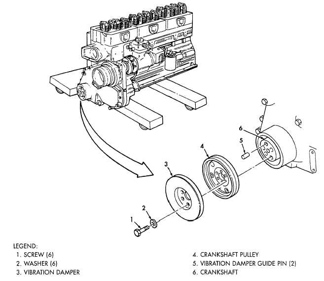
VIBRATION DAMPER AND CRANKSHAFT PULLEY INSTALLATION (Contd)
LOCATION/ITEM
ACTION
REMARKS
b. Using dial indicator gauge,
Crankshaft (6) must be kept at
measure movement of vibration
front or rear limit of thrust
damper (3) face by rotating
clearance while measuring
crankshaft (6).
movement of vibration damper (3)
face. Total indicator reading must
not exceed 0.007 in. (0.178 mm)
per 1.0 in. (25.4 mm) of the
damper radius. Remove and dis-
card vibration damper (3) if not
within limits.
FOLLOW-ON TASK: Install flexplate or flywheel, flywheel housing, and rear cover (para. 3-80).
3-607
|
|