TM 9-2815-237-34
Change 1
2-155
2-41. ENGINE ASSEMBLY FROM SUBASSEMBLIES (Cont’d)
CAUTION
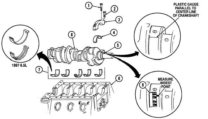
Bearing caps are numbered 1 through 5 and must be installed
in correct order, starting with number 1 at front of cylinder block.
Arrow on bearing cap must point forward or engine damage
will result.
5.
Install bearing cap (3) on cylinder block (6) with two long capscrews (1) and short capscrews (2).
Tighten capscrews (1) and (2) finger tight.
6.
Tighten all long capscrews (1) to 110 lb-ft (149 N•m). Tighten all short capscrews (2) to 100 lb-ft
(136 N•m).
7.
Remove two long capscrews (1), short capscrews (2), and bearing cap (3) from cylinder block (6).
8.
On edge of envelope (9) there is a scale which is graduated in thousandths of an inch. Without
removing gauging plastic, measure its thickness at the widest point with scale on envelope (9).
9.
If gauging plastic tapers toward the middle or ends, there is a difference in clearance indicating
taper, low spot, or irregularity of bearing or crankshaft journal. If gauging plastic indicates more
than 0.001 in. (0.025 mm) taper, measure crankshaft journal with micrometer (para. 2-17).
NOTE
If unable to obtain the proper crankshaft journal clearance, it is
acceptable to use a standard bearing with a 0.0005 in. (0.013 mm)
or 0.001 in. (0.025 mm) undersize bearing to produce clearance.
If unable to produce proper clearance, replace crankshaft.
10.
If the measurement is within the specifications of 0.002-0.004 in. (0.051-0.102 mm), go to step 11.
If measurement is not within specifications, a 0.0005 in. (0.013 mm) or 0.001 in. (0.025 mm) under-
size bearing may produce proper bearing clearance. Replace bearings and repeat steps 4 through 10.
11.
Repeat steps 4 through 10 for remaining main bearings.
|
|