TM 9-2815-237-34
2-41. ENGINE ASSEMBLY FROM SUBASSEMBLIES (Cont’d)
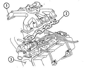
x. Intake Manifold
1. Install two gaskets (2) and intake manifold (1) on cylinder heads (3).
2. Install injection line clip (10), three injection line clips (5), and fuel supply line clamp (11) on
intake manifold (1), following assembly diagram shown.
NOTE
Perform step 3 for 6.2L engines. Perform step 4 for 6.5L engines.
3. Install four long studs (6), long capscrew (9), six studs (7), five capscrews (8), and sixteen
washers (4), following assembly diagram shown.
4. Install four long studs (6), long capscrew (9), seven studs (7), four capscrews (8), and sixteen washers (4),
following assembly diagram.
2-182
|
|