TM 9--2815--247--34
0037 00--8
FUEL INJECTOR TUBES, BRACKETS, AND ASSOCIATED PARTS --
CONTINUED
0037 00
Installation
NOTE
Fuel injector nozzle and holders must be free to rotate.
Refer to WP 0036 00.
CAUTION
Special care must be taken to ensure that all tube assem-
blies terminate at the proper cylinder. Incorrect hook--up
of the tube assemblies to a wrong cylinder or injection
pump connection would result in damage to the piston
rings and cylinder walls and severe damage to the engine
if operated under full load.
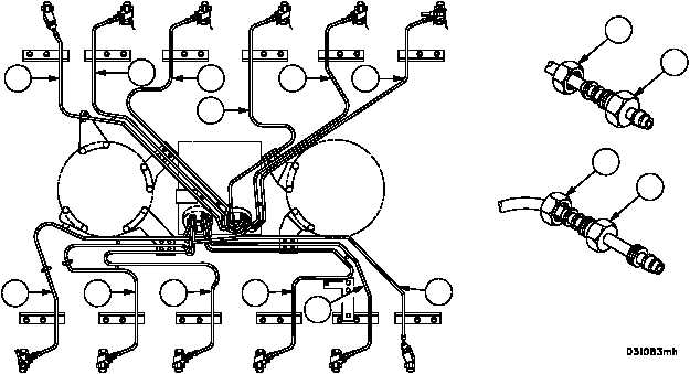
1. Install the tube assemblies (53, 54, 55, 56, 57, 58, 59, 60, 31, 61, 62, and 63) in the following sequence, starting
with the fuel injection pump end.
2. Sequence of assembly: 4R (55), 1R (58), 2R (57), 6R (53), 3R (56), 5R (54), 3L (31), 5L (62), 6L (63), 1L (59), 2L
(60), and 4L (61).
3. Complete the following steps for each tube assembly in sequence:
a. Apply a drop of lubricant (item 14, WP 0100 00) on the threads of tube adapter (69), tube fitting (70),
and two tube nuts (68).
b. Remove plugs from fuel injection pump ports.
Figure 36
RIGHT BANK
LEFT BANK
FLYWHEEL
END
DAMPER
END
53
54
55
56
57
58
59
60
31
61
62
63
6R
5R
4R
3R
2R
1R
6L
5L
4L
3L
2L
1L
68
68
69
70
|
|


