TM 9--2815--247--34
0038 00--6
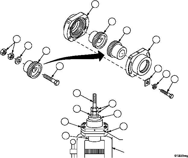
FLEXIBLE COUPLING SHAFT ASSEMBLY (METERING PUMP) REPAIR --
CONTINUED
0038 00
Inspection -- Continued
3. Install bolt (18), flat washer (19), and two nuts (20) in hub (12).
4. Temporarily assemble two hubs (5 and 12) and two sleeves (4 and 11) using four spacers (21), four lockwashers
(22), and four screws (23).
5. Clamp hub (5) in machinist’s vise.
6. Using bolt (18) as a turning device, check backlash between hubs (5 and 12) at a point 1--5/16 inches (3.3375
mm) from shaft center on any of the four flats. If backlash exceeds 0.006 inches
(0.1524 mm), replace flexible shaft coupling assembly.
7. Remove assembly from vise and remove four screws (23), four lockwashers (22), four spacers (21), two sleeves
(4 and 11), two hubs (5 and 12), two nuts (20), flatwasher (19), and screw (18).
Figure 35
20
19
12
18
4
5
12
11
21
22
23
18
19
12
11
4
5
PLACE DIAL INDICATOR HERE
TO MEASURE BACKLASH
VISE
20
|
|