TM 9--2815--247--34
0048 00--5
THROTTLE CONTROL SOLENOID ASSEMBLY AND ASSOCIATED PARTS
REPAIR -- CONTINUED
0048 00
Disassembly -- Continued
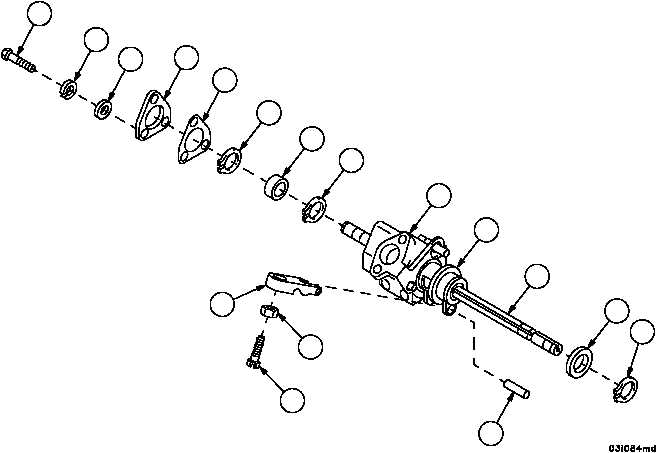
19. Remove three machine bolts (50), three lockwashers (51), and three flat washers (52) securing access cover (53)
to solenoid housing assembly (12). Discard lockwashers.
20. Remove access cover (53) and gasket (54). Discard gasket.
21. Loosen plain nut (55) and remove machine screw (56) from solenoid stop control (57).
22. Remove solenoid stop control (57) from pin (58) in solenoid control housing (44).
WARNING
23. Remove outer retaining ring (59) and flat washer (60) from straight shaft (16). Discard retaining ring.
24. Slide straight shaft (16) through solenoid housing assembly (12) and solenoid control housing (44) until bearing
(61) and two retaining rings (62) are exposed.
25. Remove outer retaining ring (62). Discard retaining ring.
26. Remove bearing (61) using a suitable puller.
Figure 47
50
51
52
53
54
62
61
62
12
44
16
60
59
58
56
55
57
|
|


