TM 9--2815--247--34
0048 00--14
THROTTLE CONTROL SOLENOID ASSEMBLY AND ASSOCIATED PARTS
REPAIR -- CONTINUED
0048 00
Assembly -- Continued
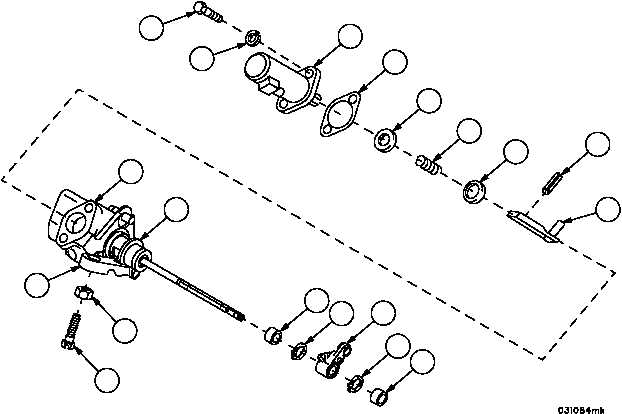
9. Install machine screw (56) and plain nut (55) in solenoid stop control (57).
10. Install spring retainer (49), spring (48), spring retainer (47), rigid connecting link (43), and spring pin (46) on elec-
trical solenoid (42).
11. Install a new gasket (45) on electrical solenoid (42).
12. Install electrical solenoid (42) on solenoid housing assembly (12) while engaging rigid connecting link (43) with
solenoid control housing (44).
13. Secure electrical solenoid (42) to solenoid housing assembly (12) using two machine bolts (40) and two new lock-
washers (41).
WARNING
14. Install two new retaining rings (39) and two bearings (38) in remote control lever (37).
Figure 47
40
41
42
45
49
48
46
43
12
44
39
38
37
39
38
56
55
57
47
|
|


