TM 9--2815--247--34
0050 00--1
GOVERNOR THROTTLE CONTROL ROD ASSEMBLY REPAIR
0050 00
THIS WORK PACKAGE COVERS:
Disassembl, Inspection, Repair, Assembly
INITIAL SETUP:
Tools and Special Tools
General mechanic’s tool kit (item 19, WP 0103 00)
Drill (item 13, WP 0103 00)
Portable electric drill (item 82, WP 0103 00)
Materials/Parts
Rod end boots (2) (item 5, WP 0102 00)
Equipment Conditions
Engine level on flat surface (WP 0021 00)
Engine cleaned and drained
(TM 9--2350--292--20)
Injection pump, transmission throttle linkage and
associated parts removed (WP 0049 00)
References
TM 9--2350--292--20
Disassembly
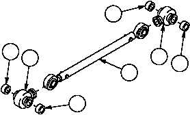
Remove two rod end boots (1) and four rod end bearing spacers (2) from governor control rod assembly (3).
Discard rod end boots.
Figure 48
1
2
3
1
2
2
2
Inspection
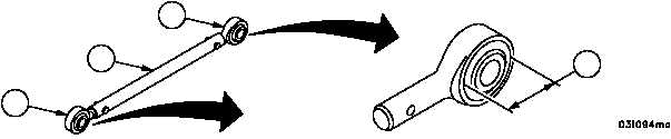
Measure the clearance (4) between ball and socket of two rod end plain bearings (5) at each end of governor
control rod assembly (3). Replace rod end plain bearing if not within the following limits.
REF
NO
POINT MEASUREMENT
SIZES AND FITS OF NEW PART
inches (mm)
WEAR LIMITS
4
Clearance between ball and socket
(parallel to shank)
0.0005 (0.0127)
0.0015 (0.0381)
0.0020 (0.0508)
Figure 48
5
5
3
4
|
|