TM 9--2815--247--34
0054 00--1
FAN DRIVE CLUTCH ASSEMBLY AND ASSOCIATED PARTS REPAIR
0054 00
THIS WORK PACKAGE COVERS:
Test, Removal, Disassembly, Inspection, Repair, Assembly, Installation
INITIAL SETUP:
Tools and Special Tools
General mechanic’s tool kit (item 19, WP 0103 00)
Mechanical puller kit (item 18, WP 0103 00)
Arbor press (item 2, WP 0103 00)
Outside micrometer caliper set (item 9, WP 0103 00)
Inside micrometer caliper set (item 10, WP 0103 00)
Telescoping gauge set (item 16, WP 0103 00)
Torque wrench (item 51, WP 0103 00)
Spacer sleeve (item 41, WP 0103 00)
Spring tester (item 47, WP 0103 00)
Torque wrench (item 50, WP 0103 00)
Machinist’s vise (item 83, WP 0103 00)
Safety goggles (item 28, WP 0103 00)
Screws (4) (item 86, WP 0103 00)
Nuts (4) (item 87, WP 0103 00)
Flat washers (4) (item 88, WP 0103 00)
Materials/Parts
Self--locking nuts (12) (item 57, WP 0102 00)
Preformed packings (2) (item 86, WP 0102 00)
Retaining rings (2) (item 124, WP 0102 00)
Wire, nonelectrical (item 22, WP 0100 00)
Lubricant (item 12, WP 0100 00)
Lubricant (item 14, WP 0100 00)
Lubricant (item 10, WP 0100 00)
Crocus cloth (item 4, WP 0100 00)
Dry--cleaning solvent (item 5, WP 0100 00)
Equipment Conditions
Engine level on flat surface (WP 0021 00)
Engine cleaned and drained
(TM 9--2350--292--20)
Fans and covers removed
(TM 9--2350--292--20)
References
TM 9--2350--292--20
NOTE
Front and rear fan drive friction clutches are interchange-
able and are removed in a similar manner. For instruc-
tional purposes this procedure covers one fan drive fric-
tion clutch. Exceptions will be noted if front and rear are
different.
Test
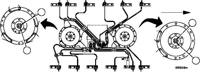
1. Install spacer sleeve (1) in place of fan and secure with fan nut (2).
Figure 52
1
2
1
2
FORWARD
|
|


