TM 9--2815--247--34
0061 00--6
CYLINDER HEAD ASSEMBLY REPAIR -- CONTINUED
0061 00
Inspection -- Continued
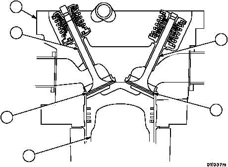
3. Inspect valve seat inserts (19 and 20) for cracks, pitted surfaces, or looseness.
NOTE
If inserts are cracked, loose, or damaged beyond repair,
the cylinder must be replaced.
4. Lightly blue face of two valve seat inserts (19 and 20) with Prussian blue and place a new valve (9 and 13) into
position on valve seat insert.
5. Rotate valves (9 and 13) one--half turn on insert and check for Prussian blue contact. Valve seat inserts (19 and
20) must show contact all around (360°), as indicated by Prussian blue transfer, to qualify as serviceable valve
seat inserts (19 and 20).
NOTE
Valve seat may be made serviceable by grinding.
NOTE
Measure cylinder bore (21) at room temperature.
Standard and oversize cylinder assemblies are identified
by the steel stamped part number located on cooling fan
shroud bracket mounting flange on exhaust port side of
the cylinder assembly (22).
Figure 9
INTAKE
EXHAUST
19
20
9
13
21
22
|
|


