TM 9--2815--247--34
0061 00--17
CYLINDER HEAD ASSEMBLY REPAIR -- CONTINUED
0061 00
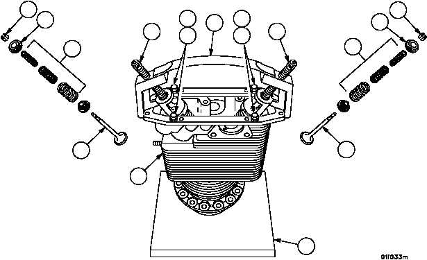
Assembly -- Continued
4. Position valve lifter assembly (3) on cylinder head assembly (1) and secure in position with four 5/16 X 1.375 (7.9375 X
34.9250 mm) rocker cover screws (4) and four 5/16--inch (7.9375 mm) flat washers (5).
WARNING
WARNING
The valves and locks are under heavy spring tension.
Exercise extreme care when installing locks, seats, and
springs. Failure to comply could result in personnel inju-
ry.
5. Compress exhaust and intake valve springs (6 and 11), intake valve spring lock (12) and exhaust valve spring
seat (7) with screws (10 and 14) and install two valve spring locks (8) in the groove of each valve (9 and 13)
stem.
6. Release valve spring compression and remove four rocker cover screws (4), four flat washers (5) and valve lifter
assembly (3) from cylinder head assembly (1).
7. Remove cylinder head assembly (1) from valve removing and inserting stand (2).
Figure 41
8
12
11
13
14
3
10
8
7
6
9
2
1
4
5
4
5
|
|