|
|
|
|

|
TM 9--2815--247--34
CONNECTING ROD ASSEMBLY AND ASSOCIATED PARTS REPAIR --
CONTINUED
0070 00
Installation -- Continued
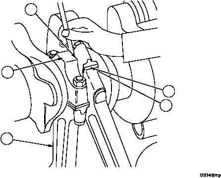
7. Check the side clearance (23) of each pair of connecting rods (3) against the following limits using a feeler gauge.
REF
NO.
POINT OF MEASUREMENT
SIZES AND FITS OF NEW PARTS
inches (mm)
WEAR LIMITS
23
Side clearance of (two) rods on
crankshaft journal
0.0090L (0.2286)
0.0170.L (0.4318)
0.0200L (0.508)
8. Disassemble and replace connecting rods (3), rod caps (2) and bearings (4 and 5) as necessary to obtain the
proper clearance.
Figure 8
3
23
2
5
4
NOTE
FOLLOW--ON MAINTENANCE:
Install oil pressure compartment baffle and associated
parts (WP 0081 00)
Install oil pump assembly (WP 0082 00)
Install oil pan assembly (WP 0080 00)
Install cylinder head assembly and piston
(WP 0059 00)
END OF TASK
0070 00--13/14 blank
|
|
|
|
|
Privacy Statement -
Copyright Information. -
Contact Us