TM 9--2815--247--34
CAMSHAFT, DRIVE GEARS, AND ASSOCIATED PARTS REPAIR --
CONTINUED
0076 00
Installation -- Continued
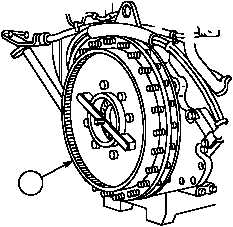
29. Rotate flywheel (47) counterclockwise approximately 1/4 turn in order to have 6R intake valve rocker arm roller on
base circle of camshaft.
47
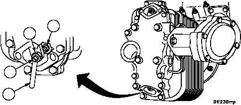
30. Using thickness gauge blade (53), set intake valve clearance on cylinder 6L or 6R to 0.010 inch (0.254 mm) by
turning the adjusting screw (54) clockwise to decrease the clearance or counterclockwise to increase the clear-
ance.
31. Check position of valve adjusting screw pad (55) to make sure seat is flat on valve stem.
32. Torque adjusting screw nut (56) to 200--225 lb--in (23--25 NSm).
Figure 8
54
55
56
53
NOTE
FOLLOW--ON MAINTENANCE:
Perform full engine timing (WP 0015 00)
Install shrouds (TM 9--2350--292--20 and WP 0053 00)
Install fuel/water separator filter bracket (L.B.)
(WP 0090 00)
Install pump drive adapter assembly (R.B.)
(WP 0078 00)
Install rocker arm covers (WP 0026 00)
Adjust valve clearance (WP 0014 00)
END OF TASK
0076 00--17/18 blank
|
|


