TM 9--2815--247--34
0082 00--16
OIL PUMP ASSEMBLY REPAIR -- CONTINUED
0082 00
Assembly -- Continued
CAUTION
Do not insert drift between impeller and housing. Dam-
age to housing may occur.
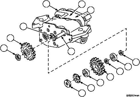
17. Position a brass rod or drift between impellers (21 and 22) through opening in housing assembly (23) to hold im-
pellers stationary.
18. Install spur gear (25) on shaft (42).
19. Apply lubricant to threads of shaft (42) and install new self--locking nut (24). Torque self--locking nut to 58--65 lb--ft
(79--88 NSm).
20. Install washer bearing (20), ball bearing (17), thrust washer (19), cluster gear (18), ball bearing (17), and new key
washer (14) on shaft (16).
21. Apply lubricant to threads of shaft (16) and install nut (15).
22. Torque nut (15) to 48--52 lb--ft (65--71 NSm).
23. Bend tabs of key washer (14) to secure nut (15).
24. Place torque wrench on nut (15). Check that less than 4 lb--in (0.452 NSm) is required to turn shaft. If more than
4 lb--in (0.452 NSm) is required to turn shaft, investigate cause of binding.
Figure 19
HIDDEN
HIDDEN
24
25
15
14
17
18
19
17
20
23
21
22
16
42
|
|