TM 9--2815--247--34
0085 00--20
ACCESSORY DRIVE HOUSING ASSEMBLY AND ASSOCIATED PARTS
REPAIR -- CONTINUED
0085 00
Adjustment -- Continued
CAUTION
Do not force shouldered shaft while installing. Damage to
the shouldered shaft and gears may occur. The shoul-
dered shaft is machined with a 24-- tooth spline on inner
end, and a 28--tooth spline on outer end. The difference
in number of teeth provides a vernier effect which makes
it possible to index the shouldered shaft so it will engage
the splines of the inner bevel gearshaft and the outer bev-
el gearshaft at some point within 360°. An accurate set-
ting is then provided without changing the relationship of
the camshaft and the crankshaft.
NOTE
It may be necessary to repeat the following operation a
number of times before splines will mate and allow shoul-
dered shaft to be inserted into position.
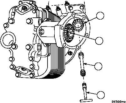
11. Maintain the position of camshaft (69) and insert shouldered shaft (77), using mechanical puller (78), and mate
splines on lower and upper bevel gearshaft (79). When splines of shouldered shaft (78) do not mate with lower
and upper bevel gearshaft (79), withdraw shouldered shaft (77) and turn slightly before again attempting insertion.
Figure 10
79
69
77
78
|
|